When we first bought 'Kahawi' the dashboard had been modified from standard, but still had the original Icknield tachometers as supplied to Freeman with the Thornycroft engines.
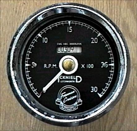
These have a set of rotary wheels that display in the dial centre, they are supposed to measure engine hours at a set running speed. The system is a simple gear-driven odometer as per any automotive speedometer, with the gear ratios calculated, such that they count in whole units and 10ths of an hour, but only if the input revs are equivalent to a constant 2,000rpm. The key point here being, when above or below these revs, the timing becomes decidedly inaccurate.
Incidentally - this is all rather irrelevant since neither of them worked anyway!
We thus had no idea how many hours the engines had been previously run, nor how many hours we were clocking up. Which also meant we had no clue as to our fuel consumption - Other than keeping detailed logs of fuel purchased and hours run per day. This was something I was quite good at (for a while) but my enthusiasm seemed to wane as the alcohol content increased. Being based on the Thames, with constant stopping and starting of engines for - or more often, waiting for- locks, anything like accurate accounts were not easy to keep.
Clearly a better method of recording engine hours was required, if only to give the engines a chance to see some fresh oil from time to time, in accordance with the manufacturers service intervals.
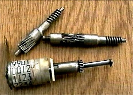
I made two failed attempts to repair the mechanics, which had a basic design flaw - The indicator wheels were made of a plastic material which absorbed moisture. In time this caused them to seize on the shaft and lock up the gearing. With 96hp behind the drive cable, this resulted in the worm drive at the base of the unit stripping its few remaining teeth very quickly.
I expect the purist would have had a phosphor-bronze replacement gear set cut and properly restored the unit to original spec, but I am not so dedicated to late sixties technology.
I could, have simply purchased ready-made marine hour-meters from the chandlers, but I didn't particularly want, indeed I did not have the space, to fit two more meters on the dashboard.
Being a techno-buff I decided there must be an electronic answer to the problem, that could be fitted within the original rev counter housing. Without too much of a search I found some Liquid Crystal Display units from Radio-Spares that would record time accurately (within 8 seconds per day) and keep this in memory when the power went off (they quote 25 years retention!)
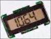
These consist of a self-contained PCB and LCD display which runs on anything from 12-48 volts DC; ideal for the battery power system aboard 'Kahawi'. Some careful physical measuring proved that with a little 'fiddling' they would just fit into the space available after the current mechanism was removed.
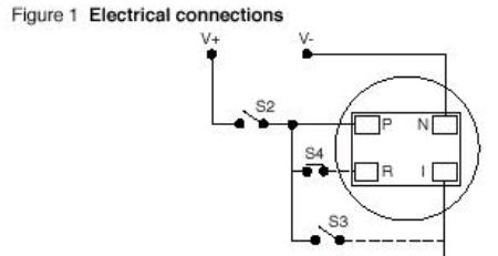
Being a basic 4-wire device, no external components were required. If ever needed, it would be possible to reset the count to zero, however I have not connected that function! 'Clocking' a boat?
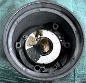
The Icknield rev-counters come apart by unscrewing the front chrome bezel, and the removing the two screws on the base, either side of the cable drive input. The pointer can be carefully removed by easing it off with a couple of small knives, it being a slight taper fit on the shaft. Luckily the end-stop is part of the rotating mechanism, so orientation for replacement is easy.
A couple of Allen keys strip down the rest of the guts. The indicator wheels and gears almost fall out at this point and can be discarded.
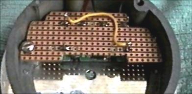
The next step was mounting the LCD. A small piece of Vero-Board was carefully cut to fit the interior frame and held in place by a screw and thread, tapped into the hole vacated by the upper bearing of the vertical gear shaft. A spacer washer keeps the board clear of the pointer return spring allowing space between the circuit board and the rear of the dial.
Some of the tracks need to be cut on the board and the power and count wires soldered in place, these were run out through a hole drilled in the base of the rev-counter housing, well clear of any rotating parts. Since the rev-counter can hardly be considered water-proof this was not a major problem, but a little silicone sealant would solve even this worry, if desired.
The dial was replaced and the LCD display carefully positioned and soldered in place hard up against the underside. The existing square hole in the dial needs to be filed larger to match the new display size, I 'blacked' up the raw edges with a felt-tip pen to disguise my metal-work.
Power is 'on' at all times the main batteries are connected to the unlit displays, I couldn't actually measure the quiescent current, it being so small. The activate, or count wire is fed from the sender side of the oil pressure warning light. This will be at earth potential with the engine stopped and at +battery volts via the bulb if there is any oil gallery pressure. This ensures that the hour-meter records actual running hours, not simply the time the ignition has been left on! We sometimes do this by accident as our engine stops are mechanical, turning off the ignition doesn't stop them. It has been known for us to lock through, carefully tending ropes etc and return to the helmsman's position some twenty minutes later to find the ignition has been left on with engines stopped!
Two years later, the hour-meters have proved a great success. We now know that we are running approximately 110 hours per engine, per annum and that our fuel consumption is ¾ gallon per hour on the Thames, with just over 2½ gallons per hour in coastal waters.
